プログラムの改良について
このサイトで以前紹介したロボットアーム制作の記事について、円筒座標系で制御できるようにプログラムを改良しましたので、紹介したいと思います。
円筒座標系で制御できると人間の感覚に近いかたちで制御できるので、操作性が良くなります。
◆ロボットアームの作り方はこちら
◆円筒座標系の計算方法はこちら
◆プログラムの実装方法、無線接続の方法はこちら
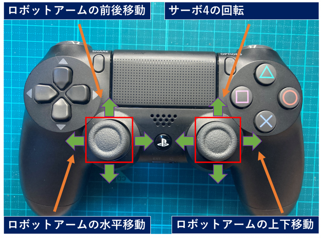
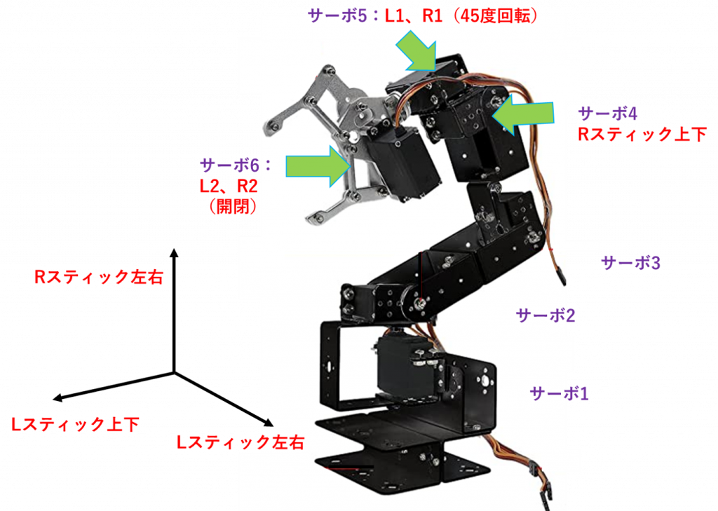
操作方法について
ロボットアームの操作方法は以下の図のとおりです。
ソースコード
有線版
無線は接続が安定しないこともあるので、有線でやりたいときがあります。
よって、今回のプログラムは有線版と無線版の両方を記載しますので、お好きな方を利用ください。
有線版はPS4のコントローラーに付属のmicro USB type BをArduino拡張シールドにそのまま指せばOKです。
※注意:PS4のコントローラーは十分に充電してから使用してください。充電不足の場合は、Arduinoから充電されることになり、動作が不安定になることがあります。
//-----PS4 有線通信用設定
#include <PS4USB.h>

// Satisfy the IDE, which needs to see the include statment in the ino too.
#ifdef dobogusinclude
#include <spi4teensy3.h>
#endif
#include <SPI.h>

USB Usb;
PS4USB PS4(&Usb);

bool printAngle, printTouch;
uint8_t oldL2Value, oldR2Value;
//-----PS4 有線通信end

//-----サーボ制御用設定
#include <PCA9685.h> //PCA9685用ヘッダーファイル
PCA9685 pwm = PCA9685(0x40);    //PCA9685のアドレス指定

//-----各変数の設定
#define SERVOMIN 150            //最小パルス幅
#define SERVOMAX 500            //最大パルス幅
#define servo_01 0              //サーボ1のピンの設定
#define servo_02 1              //サーボ2のピンの設定
#define servo_03 2              //サーボ3のピンの設定
#define servo_04 3              //サーボ4のピンの設定
#define servo_05 4              //サーボ5のピンの設定
#define servo_06 5              //サーボ6のピンの設定

double ini_arg_01 = 90;             // サーボの初期角度
double ini_arg_02 = 180;            // サーボの初期角度
double ini_arg_03 = 135;            // サーボの初期角度
double ini_arg_04 = 135;            // サーボの初期角度
double ini_arg_05 = 90;             // サーボの初期角度
double ini_arg_06 = 90;             // サーボの初期角度

double arg_01 = ini_arg_01;            // サーボの角度
double arg_02 = ini_arg_02;            // サーボの角度
double arg_03 = ini_arg_03;            // サーボの角度
double arg_04 = ini_arg_04;            // サーボの角度
double arg_05 = ini_arg_05;            // サーボの角度
double arg_06 = ini_arg_06;            // サーボの角度

double ARM_LEN2 = 105;          // アーム2の長さ105mm
double ARM_LEN3 = 100;          // アーム3の長さ100mm

//次の円筒座標位置は物理的に可能な位置か判定する 5mmの裕度を与える
double chiiki_MAX = pow((ARM_LEN2 - 5) + (ARM_LEN3 - 5), 2.0);
double chiiki_MIN = pow(ARM_LEN2 - ARM_LEN3, 2.0);

double r_now = 0;               // 円筒座標系の位置 r
double fai_now = 0;             // 円筒座標系の位置 fai
double pz_now = 0;              // 円筒座標系の位置 pz

int X_POS_L = 128;              // LスティックのX軸方向の読み取り値
int Y_POS_L = 128;              // LスティックのY軸方向の読み取り値
int X_POS_R = 128;              // RスティックのX軸方向の読み取り値
int Y_POS_R = 128;              // RスティックのY軸方向の読み取り値

int GRIP_servo5 = 128;          // サーボ5の入力(L1,R1)
int GRIP_L2 = 128;              // アームのグリップ部 閉まる方向
int GRIP_R2 = 128;              // アームのグリップ部 開く方向

int read_i = 0;
int out_i = 0;
int arg_x = 0;
//-----サーボ制御end


//-----初期設定
void setup() {
 pwm.begin();                   //初期設定 (アドレス0x40用)
 pwm.setPWMFreq(50);            //PWM周期を50Hzに設定 (アドレス0x40用)

 initial_position(arg_01, arg_02, arg_03, arg_04, arg_05, arg_06);  //ポジション初期化

  //-----PS4 有線通信
  Serial.begin(115200);

#if !defined(__MIPSEL__)
  while (!Serial); // Wait for serial port to connect - used on Leonardo, Teensy and other boards with built-in USB CDC serial connection
#endif
  if (Usb.Init() == -1) {
    Serial.print(F("\r\nOSC did not start"));
    while (1); // Halt
  }
  Serial.print(F("\r\nPS4 USB Library Started"));
  //-----PS4 有線通信
}

//-----メインループ
void loop() {
  //-----PS4 有線通信
  Usb.Task();
  //ボタンの入力を取得
  if (PS4.connected()) {

    //ボタンの入力を取得
    if (PS4.connected()) {
    //-----L1、R1の入力値を200 or 0に変換
      if (PS4.getButtonClick(L1))
        GRIP_servo5 = 200;
      if (PS4.getButtonClick(R1))
        GRIP_servo5 = 0;
    }

    //-----6回に1回コントローラーのアナログ入力を取得する(過敏に反応しすぎるため)
    if(read_i == 0){
      X_POS_L = PS4.getAnalogHat(LeftHatX);  // LスティックのX軸方向のアナログ値を読み取る
      Y_POS_L = PS4.getAnalogHat(LeftHatY);  // LスティックのY軸方向のアナログ値を読み取る
      X_POS_R = PS4.getAnalogHat(RightHatX); // RスティックのX軸方向のアナログ値を読み取る
      Y_POS_R = PS4.getAnalogHat(RightHatY); // RスティックのY軸方向のアナログ値を読み取る

      GRIP_L2 = PS4.getAnalogButton(L2);     // L2のアナログ値を読み取る
      GRIP_R2 = PS4.getAnalogButton(R2);     // R2のアナログ値を読み取る
    }

    //-----オプションボタンが押されたら通信終了_Aruduinoリセット
    if (PS4.getButtonClick(OPTIONS)) {
      Serial.print(F("\r\nOptions"));
      //PS4.disconnect();           //Bluetooth通信を遮断

      /*Arduinoリセット時にサーボ2が暴れる可能性があるので、
        5回に分けて初期位置に戻す*/
      arg_x = (180 - arg_02)/5;
      for(int j=0; j < 5; j++){
          arg_02 += arg_x;
          servo_write(servo_02, arg_02);
          delay(500);
      }
      software_reset();         //Arduinoリセット
    }
  }

  read_i = read_i + 1;

  if(read_i == 3){
    read_i = 0;
  }

  //-----PS4 有線通信

  //円筒座標系の位置計算
  calculate_rfaipz(&r_now, &fai_now, &pz_now, arg_01, arg_02, arg_03);

  //円筒座標系の移動量Y_POS_L、Y_POS_Rからarg_02、arg_03を計算
  inverse_kinematics(Y_POS_L, Y_POS_R, r_now, pz_now, arg_02, arg_03, &arg_02, &arg_03);

  //-----サーボモーター用にコントローラー入力→角度_変換
  arg_01 = arg_01 + convert_01(X_POS_L, arg_01);
  arg_04 = arg_04 + convert_03(X_POS_R, arg_04);
  arg_05 = arg_05 + 20 * convert_01(GRIP_servo5, arg_05); //2度×20=40度ずつ制御
  arg_06 = arg_06 + convert_04(GRIP_L2, GRIP_R2, arg_06);


  double r_pre = r_now;
  double pz_pre = pz_now;

  //円筒座標系の位置計算
  calculate_rfaipz(&r_now, &fai_now, &pz_now, arg_01, arg_02, arg_03);

  Serial.print(r_now);
  Serial.print("  ");
  //Serial.print(fai_now);
  Serial.print("  ");
  Serial.println(pz_now);

  //-----サーボ制御(関数呼び出し)
  servo_write(servo_01, arg_01);
  servo_write(servo_02, arg_02);
  servo_write(servo_03, arg_03);
  servo_write(servo_04, arg_04);
  servo_write(servo_05, arg_05);
  servo_write(servo_06, arg_06);

  //-----入力リセット
  X_POS_L = 128;      // LスティックのX軸方向の読み取り値
  Y_POS_L = 128;      // LスティックのY軸方向の読み取り値
  X_POS_R = 128;      // RスティックのX軸方向の読み取り値
  Y_POS_R = 128;      // RスティックのY軸方向の読み取り値

  GRIP_L2 = 128;      // アームのグリップ部 閉まる方向
  GRIP_R2 = 128;      // アームのグリップ部 開く方向
  GRIP_servo5 = 128;  // サーボ5

  //delay(300);

}
//-----メインループend以下、呼び出し用の関数です。
私は見やすいように関数を別ファイルにしていますが、同一ファイルにそのままコピペでもOKです。
/////-----呼び出し用の関数まとめ-----/////

//-----サーボ出力用_サーボ番号、角度→出力_関数
void servo_write(int ch, double ang){ //動かすサーボチャンネルと角度を指定
  ang = map(ang, 0, 180, SERVOMIN, SERVOMAX); //角度(0~180)をPWMのパルス幅(150~500)に変換
  pwm.setPWM(ch, 0, ang);
}

//-----サーボ位置初期化用関数
void initial_position(double arg_01, double arg_02, double arg_03, double arg_04, double arg_05, double arg_06){ //動かすサーボチャンネルと角度を指定

//  各サーボの初期値
  arg_01 = ini_arg_01;   // サーボの角度
  arg_02 = ini_arg_02;   // サーボの角度
  arg_03 = ini_arg_03;   // サーボの角度
  arg_04 = ini_arg_04;   // サーボの角度
  arg_05 = ini_arg_05;   // サーボの角度
  arg_06 = ini_arg_06;   // サーボの角度

  //サーボ出力
  servo_write(servo_01, arg_01);
  delay(500);
  servo_write(servo_02, arg_02);
  delay(500);
  servo_write(servo_03, arg_03);
  delay(500);
  servo_write(servo_04, arg_04);
  delay(500);
  servo_write(servo_05, arg_05);
  delay(500);
  servo_write(servo_06, arg_06);
  delay(500);
}

//-----リセット用関数
void software_reset() {
  asm volatile ("  jmp 0");
}

//-----サーボ1、サーボ5用_コントローラー入力→角度_変換関数
int convert_01(int input_x, double arg_x){
  if(arg_x == 170 && input_x > 190){      //サーボ角度制御、170度以下
    return 0;
  }
  else if (arg_x == 10 && input_x < 65){  //サーボ角度制御、10度以上
    return 0;
  }
  else if(input_x > 190){     //2度ずつ増加
    return 1;
  }
  else if(input_x < 65){      //2度ずつ減少
    return -1;
  }
  else{
    return 0;
  }
}

//-----サーボ2用_コントローラー入力→角度_変換関数
int convert_02(int input_x, double arg_x){
  if(arg_x == 180 && input_x > 190){      //サーボ角度制御、180度以下
    return 0;
  }
  else if (arg_x == 45 && input_x < 65){  //サーボ角度制御、45度以上
    return 0;
  }
  else if(input_x > 190){     //1度ずつ増加
    return 1;
  }
  else if(input_x < 65){      //1度ずつ減少
    return -1;
  }
  else{
    return 0;
  }
}

//-----サーボ4用_コントローラー入力→角度_変換関数
int convert_03(int input_x, double arg_x){
  if(arg_x == 135 && input_x < 65){        //サーボ角度制御、135度以下
    return 0;
  }
  else if (arg_x == 0 && input_x > 190){  //サーボ角度制御、45度以上
    return 0;
  }
  else if(input_x > 190){     //1度ずつ減少
    return -1;
  }
  else if(input_x < 65){      //1度ずつ増加
    return 1;
  }
  else{
    return 0;
  }
}

//サーボ6用_コントローラー入力→角度_変換関数
int convert_04(int input_L, int input_R, double arg_x){
  if(arg_x == 90 && input_L > 190){        //サーボ角度制御、90度以下
    return 0;
  }
  else if (arg_x == 20 && input_R > 190){  //サーボ角度制御、20度以上
    return 0;
  }
  else if(input_L > 190 && input_R > 190){  //L2、R2同時押しは無効化
    return 0;
  }
  else if(input_L > 190){     //10度ずつ増加
    return 5;
  }
  else if(input_R > 190){     //10度ずつ減少
    return -5;
  }
  else{
    return 0;
  }
}

//円筒座標系の座標位置を計算する関数
void calculate_rfaipz(double *r_now, double *fai_now, double *pz_now, double arg_x1, double arg_x2, double arg_x3){
  double r_x = 0;
  double fai_x = 0;
  double pz_x = 0;

  // double r_fai_pz_x[] = {0,0,0};

  //サーボの角度を 度→ラジアンに変換
  double rad_arg_x1 = radians(arg_x1);
  double rad_arg_x2 = radians(arg_x2);
  double rad_arg_x3 = radians(arg_x3);

  r_x = ARM_LEN2 * cos(rad_arg_x2) + ARM_LEN3 * cos(rad_arg_x2 - rad_arg_x3);
  fai_x = arg_x1;
  pz_x = ARM_LEN2 * sin(rad_arg_x2) + ARM_LEN3 * sin(rad_arg_x2 - rad_arg_x3);

  *r_now = r_x;
  *fai_now = fai_x;
  *pz_now = pz_x;

  //return r_fai_pz_x;
}

//-----Y_POS_L、Y_POS_R用_コントローラー入力→円筒座標系のr軸に変換関数
int convert_02r(int input_x){
  if(input_x > 190){     //1mmずつ増加
    //Serial.print("plus");
    return -1;
  }
  else if(input_x < 65){      //1mmずつ減少
    //Serial.print("minus");
    return 1;
  }
  else{
    return 0;
  }
}

//円筒座標系の逆運動学
void inverse_kinematics(double r_now_dx, double pz_now_dx, double r_now_x, double pz_now_x, double arg_02_x, double arg_03_x, double *arg_02, double *arg_03){

  //次の円筒座標位置からサーボモーター02,03の角度を求める
  double arg_02_next = arg_02_x;
  double arg_03_next = arg_03_x;

  //現時点での座標位置を保存
  double r_now_pre = r_now_x;
  double pz_now_pre = pz_now_x;

  //現在の円筒座標位置とコントローラーの入力から次の円筒座標位置を求める
  r_now_x = r_now_x + convert_02r(r_now_dx);
  pz_now_x =  pz_now_x + convert_02r(pz_now_dx);

  //値域が制御範囲内か確認
  double chiiki_now = pow(r_now_x, 2.0) + pow(pz_now_x, 2.0);
  //制御範囲内でなければ移動しない
  if(chiiki_now > chiiki_MAX){
    r_now_x = r_now_pre;
    pz_now_x = pz_now_pre;

    arg_02_next = arg_02_x;
    arg_03_next = arg_03_x;
    Serial.print("MAX numa!");
  }
  else if(chiiki_now < chiiki_MIN) {
    r_now_x = r_now_pre;
    pz_now_x = pz_now_pre;

    arg_02_next = arg_02_x;
    arg_03_next = arg_03_x;
    Serial.print("MIN numa!");
  }
  else{
    //逆運動学の公式より
    arg_03_next = abs( acos( (pow(r_now_x, 2.0) + pow(pz_now_x, 2.0) - (pow(ARM_LEN2, 2.0) + pow(ARM_LEN3, 2.0)))/(2 * ARM_LEN2 * ARM_LEN3) ) );

    double S3 = sin(arg_03_next);
    double C3 = cos(arg_03_next);
    arg_02_next = atan2( (ARM_LEN3*S3*r_now_x + (ARM_LEN2 + ARM_LEN3*C3)*pz_now_x ),( (ARM_LEN2 + ARM_LEN3*C3)*r_now_x - ARM_LEN3*S3*pz_now_x) );

    //ラジアン→度に変換
    arg_02_next = degrees(arg_02_next);
    arg_03_next = degrees(arg_03_next);

    //Serial.print("gyakuunndougaku!");
  }


  //サーボ02用の角度 制御範囲内か確認
  if(arg_02_next > 180){
    *arg_02 = arg_02_x;
  }
  else if(arg_02_next < 0){
    *arg_02 = arg_02_x;
    //Serial.print("MIN numa!");
  }
  else{
    *arg_02 = arg_02_next;
  }

  //サーボ03用の角度 制御範囲内か確認
  if(arg_03_next > 135){
    *arg_03 = arg_03_x;
  }
  else if(arg_03_next < 0){
    *arg_03 = arg_03_x;
  }
  else{
    *arg_03 = arg_03_next;
  }

}無線版
無線は接続が安定しないこともありますが、コードレスはやはり便利です。
無線版のプログラムも以下に記載しますので、ご利用ください。
※注意:PS4のコントローラーが白点滅して繋がらない場合は、背面のリセットボタンを押してから再接続するとつながることがあります。
//-----PS4 Bluetooth通信用設定
#include <PS4BT.h>
#include <usbhub.h>
// Satisfy the IDE, which needs to see the include statment in the ino too.
#ifdef dobogusinclude
#include <spi4teensy3.h>
#endif
#include <SPI.h>
USB Usb;
BTD Btd(&Usb); // You have to create the Bluetooth Dongle instance like so
/* You can create the instance of the PS4BT class in two ways */
PS4BT PS4(&Btd, PAIR);
bool printAngle, printTouch;
uint8_t oldL2Value, oldR2Value;
//-----PS4 Bluetooth通信end
//-----サーボ制御用設定
#include <PCA9685.h> //PCA9685用ヘッダーファイル
PCA9685 pwm = PCA9685(0x40); //PCA9685のアドレス指定
//-----各変数の設定
#define SERVOMIN 150 //最小パルス幅
#define SERVOMAX 500 //最大パルス幅
#define servo_01 0 //サーボ1のピンの設定
#define servo_02 1 //サーボ2のピンの設定
#define servo_03 2 //サーボ3のピンの設定
#define servo_04 3 //サーボ4のピンの設定
#define servo_05 4 //サーボ5のピンの設定
#define servo_06 5 //サーボ6のピンの設定
double ini_arg_01 = 90; // サーボの初期角度
double ini_arg_02 = 180; // サーボの初期角度
double ini_arg_03 = 135; // サーボの初期角度
double ini_arg_04 = 135; // サーボの初期角度
double ini_arg_05 = 90; // サーボの初期角度
double ini_arg_06 = 90; // サーボの初期角度
double arg_01 = ini_arg_01; // サーボの角度
double arg_02 = ini_arg_02; // サーボの角度
double arg_03 = ini_arg_03; // サーボの角度
double arg_04 = ini_arg_04; // サーボの角度
double arg_05 = ini_arg_05; // サーボの角度
double arg_06 = ini_arg_06; // サーボの角度
double ARM_LEN2 = 105; // アーム2の長さ105mm
double ARM_LEN3 = 100; // アーム3の長さ100mm
//次の円筒座標位置は物理的に可能な位置か判定する 5mmの裕度を与える
double chiiki_MAX = pow((ARM_LEN2 - 5) + (ARM_LEN3 - 5), 2.0);
double chiiki_MIN = pow(ARM_LEN2 - ARM_LEN3, 2.0);
double r_now = 0; // 円筒座標系の位置 r
double fai_now = 0; // 円筒座標系の位置 fai
double pz_now = 0; // 円筒座標系の位置 pz
int X_POS_L = 128; // LスティックのX軸方向の読み取り値
int Y_POS_L = 128; // LスティックのY軸方向の読み取り値
int X_POS_R = 128; // RスティックのX軸方向の読み取り値
int Y_POS_R = 128; // RスティックのY軸方向の読み取り値
int GRIP_servo5 = 128; // サーボ5の入力(L1,R1)
int GRIP_L2 = 128; // アームのグリップ部 閉まる方向
int GRIP_R2 = 128; // アームのグリップ部 開く方向
int read_i = 0;
int out_i = 0;
int arg_x = 0;
//-----サーボ制御end
//-----初期設定
void setup() {
pwm.begin(); //初期設定 (アドレス0x40用)
pwm.setPWMFreq(50); //PWM周期を50Hzに設定 (アドレス0x40用)
initial_position(arg_01, arg_02, arg_03, arg_04, arg_05, arg_06); //ポジション初期化
//-----PS4 Bluetooth通信
Serial.begin(115200); // シリアル通信の開始
#if !defined(__MIPSEL__)
// Wait for serial port to connect - used on Leonardo,
// Teensy and other boards with built-in USB CDC serial connection
while (!Serial);
#endif
if (Usb.Init() == -1) {
Serial.print(F("\r\nOSC did not start"));
while (1); // Halt
}
Serial.print(F("\r\nPS4 Bluetooth Library Started"));
//-----PS4 Bluetooth通信
}
//-----メインループ
void loop() {
//-----PS4 Bluetooth通信
Usb.Task();
//ボタンの入力を取得
if (PS4.connected()) {
//ボタンの入力を取得
if (PS4.connected()) {
//-----L1、R1の入力値を200 or 0に変換
if (PS4.getButtonClick(L1))
GRIP_servo5 = 200;
if (PS4.getButtonClick(R1))
GRIP_servo5 = 0;
}
//-----6回に1回コントローラーのアナログ入力を取得する(過敏に反応しすぎるため)
if(read_i == 0){
X_POS_L = PS4.getAnalogHat(LeftHatX); // LスティックのX軸方向のアナログ値を読み取る
Y_POS_L = PS4.getAnalogHat(LeftHatY); // LスティックのY軸方向のアナログ値を読み取る
X_POS_R = PS4.getAnalogHat(RightHatX); // RスティックのX軸方向のアナログ値を読み取る
Y_POS_R = PS4.getAnalogHat(RightHatY); // RスティックのY軸方向のアナログ値を読み取る
GRIP_L2 = PS4.getAnalogButton(L2); // L2のアナログ値を読み取る
GRIP_R2 = PS4.getAnalogButton(R2); // R2のアナログ値を読み取る
}
//-----オプションボタンが押されたら通信終了_Aruduinoリセット
if (PS4.getButtonClick(OPTIONS)) {
Serial.print(F("\r\nOptions"));
//PS4.disconnect(); //Bluetooth通信を遮断
/*Arduinoリセット時にサーボ2が暴れる可能性があるので、
5回に分けて初期位置に戻す*/
arg_x = (180 - arg_02)/5;
for(int j=0; j < 5; j++){
arg_02 += arg_x;
servo_write(servo_02, arg_02);
delay(500);
}
software_reset(); //Arduinoリセット
}
}
read_i = read_i + 1;
if(read_i == 3){
read_i = 0;
}
//-----PS4 Bluetooth通信
//円筒座標系の位置計算
calculate_rfaipz(&r_now, &fai_now, &pz_now, arg_01, arg_02, arg_03);
//円筒座標系の移動量Y_POS_L、Y_POS_Rからarg_02、arg_03を計算
inverse_kinematics(Y_POS_L, Y_POS_R, r_now, pz_now, arg_02, arg_03, &arg_02, &arg_03);
//-----サーボモーター用にコントローラー入力→角度_変換
arg_01 = arg_01 + convert_01(X_POS_L, arg_01);
arg_04 = arg_04 + convert_03(X_POS_R, arg_04);
arg_05 = arg_05 + 20 * convert_01(GRIP_servo5, arg_05); //2度×20=40度ずつ制御
arg_06 = arg_06 + convert_04(GRIP_L2, GRIP_R2, arg_06);
double r_pre = r_now;
double pz_pre = pz_now;
//円筒座標系の位置計算
calculate_rfaipz(&r_now, &fai_now, &pz_now, arg_01, arg_02, arg_03);
Serial.print(r_now);
Serial.print(" ");
//Serial.print(fai_now);
Serial.print(" ");
Serial.println(pz_now);
//-----サーボ制御(関数呼び出し)
servo_write(servo_01, arg_01);
servo_write(servo_02, arg_02);
servo_write(servo_03, arg_03);
servo_write(servo_04, arg_04);
servo_write(servo_05, arg_05);
servo_write(servo_06, arg_06);
//-----入力リセット
X_POS_L = 128; // LスティックのX軸方向の読み取り値
Y_POS_L = 128; // LスティックのY軸方向の読み取り値
X_POS_R = 128; // RスティックのX軸方向の読み取り値
Y_POS_R = 128; // RスティックのY軸方向の読み取り値
GRIP_L2 = 128; // アームのグリップ部 閉まる方向
GRIP_R2 = 128; // アームのグリップ部 開く方向
GRIP_servo5 = 128; // サーボ5
//delay(300);
}
//-----メインループend以下、呼び出し用の関数です。
私は見やすいように関数を別ファイルにしていますが、同一ファイルにそのままコピペでもOKです。
/////-----呼び出し用の関数まとめ-----/////

//-----サーボ出力用_サーボ番号、角度→出力_関数
void servo_write(int ch, double ang){ //動かすサーボチャンネルと角度を指定
  ang = map(ang, 0, 180, SERVOMIN, SERVOMAX); //角度(0~180)をPWMのパルス幅(150~500)に変換
  pwm.setPWM(ch, 0, ang);
}

//-----サーボ位置初期化用関数
void initial_position(double arg_01, double arg_02, double arg_03, double arg_04, double arg_05, double arg_06){ //動かすサーボチャンネルと角度を指定

//  各サーボの初期値
  arg_01 = ini_arg_01;   // サーボの角度
  arg_02 = ini_arg_02;   // サーボの角度
  arg_03 = ini_arg_03;   // サーボの角度
  arg_04 = ini_arg_04;   // サーボの角度
  arg_05 = ini_arg_05;   // サーボの角度
  arg_06 = ini_arg_06;   // サーボの角度

  //サーボ出力
  servo_write(servo_01, arg_01);
  delay(500);
  servo_write(servo_02, arg_02);
  delay(500);
  servo_write(servo_03, arg_03);
  delay(500);
  servo_write(servo_04, arg_04);
  delay(500);
  servo_write(servo_05, arg_05);
  delay(500);
  servo_write(servo_06, arg_06);
  delay(500);
}

//-----リセット用関数
void software_reset() {
  asm volatile ("  jmp 0");
}

//-----サーボ1、サーボ5用_コントローラー入力→角度_変換関数
int convert_01(int input_x, double arg_x){
  if(arg_x == 170 && input_x > 190){      //サーボ角度制御、170度以下
    return 0;
  }
  else if (arg_x == 10 && input_x < 65){  //サーボ角度制御、10度以上
    return 0;
  }
  else if(input_x > 190){     //2度ずつ増加
    return 1;
  }
  else if(input_x < 65){      //2度ずつ減少
    return -1;
  }
  else{
    return 0;
  }
}

//-----サーボ2用_コントローラー入力→角度_変換関数
int convert_02(int input_x, double arg_x){
  if(arg_x == 180 && input_x > 190){      //サーボ角度制御、180度以下
    return 0;
  }
  else if (arg_x == 45 && input_x < 65){  //サーボ角度制御、45度以上
    return 0;
  }
  else if(input_x > 190){     //1度ずつ増加
    return 1;
  }
  else if(input_x < 65){      //1度ずつ減少
    return -1;
  }
  else{
    return 0;
  }
}

//-----サーボ4用_コントローラー入力→角度_変換関数
int convert_03(int input_x, double arg_x){
  if(arg_x == 135 && input_x < 65){        //サーボ角度制御、135度以下
    return 0;
  }
  else if (arg_x == 0 && input_x > 190){  //サーボ角度制御、45度以上
    return 0;
  }
  else if(input_x > 190){     //1度ずつ減少
    return -1;
  }
  else if(input_x < 65){      //1度ずつ増加
    return 1;
  }
  else{
    return 0;
  }
}

//サーボ6用_コントローラー入力→角度_変換関数
int convert_04(int input_L, int input_R, double arg_x){
  if(arg_x == 90 && input_L > 190){        //サーボ角度制御、90度以下
    return 0;
  }
  else if (arg_x == 20 && input_R > 190){  //サーボ角度制御、20度以上
    return 0;
  }
  else if(input_L > 190 && input_R > 190){  //L2、R2同時押しは無効化
    return 0;
  }
  else if(input_L > 190){     //10度ずつ増加
    return 5;
  }
  else if(input_R > 190){     //10度ずつ減少
    return -5;
  }
  else{
    return 0;
  }
}

//円筒座標系の座標位置を計算する関数
void calculate_rfaipz(double *r_now, double *fai_now, double *pz_now, double arg_x1, double arg_x2, double arg_x3){
  double r_x = 0;
  double fai_x = 0;
  double pz_x = 0;

  // double r_fai_pz_x[] = {0,0,0};

  //サーボの角度を 度→ラジアンに変換
  double rad_arg_x1 = radians(arg_x1);
  double rad_arg_x2 = radians(arg_x2);
  double rad_arg_x3 = radians(arg_x3);

  r_x = ARM_LEN2 * cos(rad_arg_x2) + ARM_LEN3 * cos(rad_arg_x2 - rad_arg_x3);
  fai_x = arg_x1;
  pz_x = ARM_LEN2 * sin(rad_arg_x2) + ARM_LEN3 * sin(rad_arg_x2 - rad_arg_x3);

  *r_now = r_x;
  *fai_now = fai_x;
  *pz_now = pz_x;

  //return r_fai_pz_x;
}

//-----Y_POS_L、Y_POS_R用_コントローラー入力→円筒座標系のr軸に変換関数
int convert_02r(int input_x){
  if(input_x > 190){     //1mmずつ増加
    //Serial.print("plus");
    return -1;
  }
  else if(input_x < 65){      //1mmずつ減少
    //Serial.print("minus");
    return 1;
  }
  else{
    return 0;
  }
}

//円筒座標系の逆運動学
void inverse_kinematics(double r_now_dx, double pz_now_dx, double r_now_x, double pz_now_x, double arg_02_x, double arg_03_x, double *arg_02, double *arg_03){

  //次の円筒座標位置からサーボモーター02,03の角度を求める
  double arg_02_next = arg_02_x;
  double arg_03_next = arg_03_x;

  //現時点での座標位置を保存
  double r_now_pre = r_now_x;
  double pz_now_pre = pz_now_x;

  //現在の円筒座標位置とコントローラーの入力から次の円筒座標位置を求める
  r_now_x = r_now_x + convert_02r(r_now_dx);
  pz_now_x =  pz_now_x + convert_02r(pz_now_dx);

  //値域が制御範囲内か確認
  double chiiki_now = pow(r_now_x, 2.0) + pow(pz_now_x, 2.0);
  //制御範囲内でなければ移動しない
  if(chiiki_now > chiiki_MAX){
    r_now_x = r_now_pre;
    pz_now_x = pz_now_pre;

    arg_02_next = arg_02_x;
    arg_03_next = arg_03_x;
    Serial.print("MAX numa!");
  }
  else if(chiiki_now < chiiki_MIN) {
    r_now_x = r_now_pre;
    pz_now_x = pz_now_pre;

    arg_02_next = arg_02_x;
    arg_03_next = arg_03_x;
    Serial.print("MIN numa!");
  }
  else{
    //逆運動学の公式より
    arg_03_next = abs( acos( (pow(r_now_x, 2.0) + pow(pz_now_x, 2.0) - (pow(ARM_LEN2, 2.0) + pow(ARM_LEN3, 2.0)))/(2 * ARM_LEN2 * ARM_LEN3) ) );

    double S3 = sin(arg_03_next);
    double C3 = cos(arg_03_next);
    arg_02_next = atan2( (ARM_LEN3*S3*r_now_x + (ARM_LEN2 + ARM_LEN3*C3)*pz_now_x ),( (ARM_LEN2 + ARM_LEN3*C3)*r_now_x - ARM_LEN3*S3*pz_now_x) );

    //ラジアン→度に変換
    arg_02_next = degrees(arg_02_next);
    arg_03_next = degrees(arg_03_next);

    //Serial.print("gyakuunndougaku!");
  }


  //サーボ02用の角度 制御範囲内か確認
  if(arg_02_next > 180){
    *arg_02 = arg_02_x;
  }
  else if(arg_02_next < 0){
    *arg_02 = arg_02_x;
    //Serial.print("MIN numa!");
  }
  else{
    *arg_02 = arg_02_next;
  }

  //サーボ03用の角度 制御範囲内か確認
  if(arg_03_next > 135){
    *arg_03 = arg_03_x;
  }
  else if(arg_03_next < 0){
    *arg_03 = arg_03_x;
  }
  else{
    *arg_03 = arg_03_next;
  }

}Arduinoの動かし方から学びたい方へ
Arduinoの動かし方等、プログラミングから学びたい方にはUdemyをおすすめします。
私も社会人になってからHTML、CSS、Javascript、PHPを勉強しましたが、その時も有料の動画受講サービスを使って学習するのが効率が良かったです。
忙しい社会人からすると動画で勉強できるのは非常にありがたいです。
・習いごととしては価格が安い。(合宿や対面などの習いごとより安いです)
・動画で受講できるので、自分のペースで学習できる。(倍速設定もあり)
・受講期間はないため、何度でも受講できる。
・隙間時間を活用できる。
・コースごとに評価も見れるため、学習内容を信用できる。
アルディーノマイコンと電子工作入門【Udemy】
| 講座名 | アルディーノマイコンと電子工作入門 |
| おすすめ度 | ★★★★☆ (4.5) |
| 対象者 | マイコンの初心者・入門者。電子工作の初心者・入門者。 マイコンのプログラミングをこれから始めたい人。 電子工作をこれから始めたい人。 |
| 料金 | 13,800円 セール時 1,600円 |
| 時間 | 4.5時間 |
| 学習内容 | 新バージョンのアルディーノIDE2.0に対応! Arduino(アルディーノ)のマイコンボードを使って電子工作を学びます。 マイコンボードでLEDを点灯したり、センサーを使って測定したり、音を鳴らしたり、サーボモータを回したりします。 |
まとめ
今回は、円筒座標系のプログラムを紹介しました。
今回紹介したプログラムもまだまだよくないところはあるので、適宜修正していこうと思います。
このシリーズの他の記事
| この記事のシリーズ一覧 | |
| ◆◆◆ STEP1_基礎編:とにかく動かす ◆◆◆ | |
| その① | コスパ最強!? ロボットアームの作り方_その① |
| その② | コスパ最強!?ロボットアームの作り方_その②__テスト回路の作り方 |
| その③ | コスパ最強!?ロボットアームの作り方_その③_機構部の組み立て方 |
| その④ | コスパ最強!?ロボットアームの作り方_その④_回路部分の作り方 |
| その⑤ | コスパ最強!?ロボットアームの作り方_その⑤_プログラム |
| ◆◆◆ STEP2_実用化編:安定して動かす ◆◆◆ | |
| その⑥ | コスパ最強!?ロボットアームの作り方_その⑥_サーボ交換と電源強化【近日公開予定】 |
| その⑦ | コスパ最強!?ロボットアームの作り方_その⑦_プログラム更新 |
| その⑧ | コスパ最強!?ロボットアームの作り方_その⑧_円筒座標系の逆運動学 |
| ◆◆◆ STEP3_応用編:自在に動かす ◆◆◆ | |
| 準備中 | |
| ◆◆◆ Extra_おまけ編:カスタムして遊ぶ ◆◆◆ | |
| おまけ① | ロボットアームにドラゴンの頭をつけてみた |
この記事はおまけ①です。
必要な部品一覧

| Amazonリンク | 購入にあたって解説 | |
| ① | ロボットアーム | 在庫切れの場合はこちら (思いのほか多くの方に購入していただいたようで 在庫切れの場合があるようです。) |
| ② | Arduino 本体 | ②’を購入の場合不要。 |
| ②’ | Arduino学習キット(②、⑦、⑨セット) | ②、⑦、⑨セット こちらをおすすめします。 |
| ③ | PS4 コントローラー | |
| ④ | Arduino USB shield | 在庫切れの場合はこちら |
| ⑤ | USB Bluetooth アダプタ | 技適マークあり(日本で使用OKです。) |
| ⑥ | モータードライバー | |
| ⑦ | Arduino 用ワイヤーゲージ | ②’を購入の場合不要。 |
| ⑦⁺ | サーボ延長ケーブル | +αであると配線がすっきりします。 |
| ⑧ | ACアダプター | |
| ⑨ | モータードライバー用電源モジュール | ②’を購入の場合不要。 |
| ⑩ | クリップ | 普通のクリップ1個あればOKです。 |
| ⑪ | 木板 | ホームセンターに売っているものでOKです。 30cm×20cm程度。 |
| ⑫ | タッピングねじ M3×10 | これもホームセンターに売っているものでOKです。 |
コメント